How to Identify Common Defects in Automotive Bumper Molding

Time:2026-09-19 Author:Amelia
0%

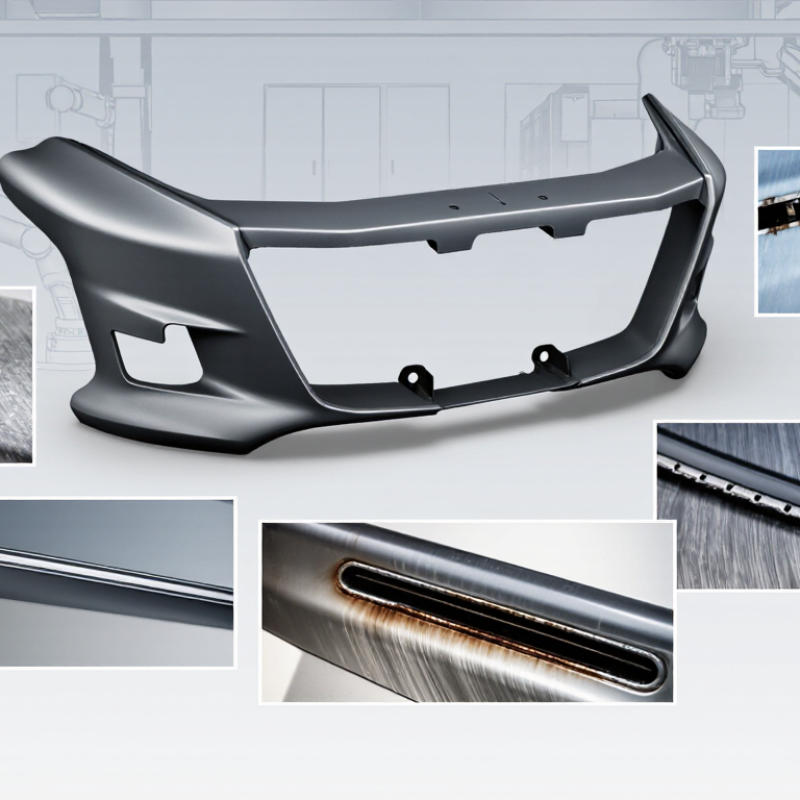
Automotive bumper molding can look simple, yet small process errors often create visible and costly defects. A cloudy surface, uneven gloss, or a thin flash line may reveal problems inside the mold. If you have asked, “what are the common defects in automotive bumper molding,” the answer begins with careful observation. Typical defects include sink marks, short shots, weld lines, burn marks, warpage, flow marks, and dimensional instability. Each defect leaves a different signature.

In production environments, technicians inspect the bumper under consistent lighting and compare it with approved samples. They check the gate area, ribs, corners, and cooling channels. A sink mark near a thick rib may indicate uneven cooling or insufficient packing pressure. Warpage can result from mold temperature differences, poor part design, or unbalanced cooling. Short shots may point to restricted flow, low melt temperature, or inadequate injection speed. Small clues matter. The surface tells.

Reliable identification requires more than visual judgment. Teams should record machine settings, material batch details, mold temperature, and cycle time. Dimensional checks and controlled trial runs can confirm the suspected cause. One inspection can mislead. A defect may involve several factors, including recycled content, moisture, venting, or worn tooling. Practical experience helps, but it should support measurement rather than replace it. This guide explains how to recognize common bumper molding defects, connect their appearance with likely causes, and choose a more disciplined inspection approach. Not every defect has one clear answer. Good troubleshooting remains careful, repeatable, and open to correction.
How to Identify Common Defects in Automotive Bumper Molding

Identify PP/TPO Bumper Materials and 2–4 mm Wall-Thickness Standards

Automotive bumper molding starts with correct material identification. Polypropylene (PP) usually shows a density near 0.90–0.91 g/cm³ under ISO 1183 testing. TPO blends commonly fall near 0.90–0.96 g/cm³, depending on rubber and mineral content. Density alone is not enough. Use FTIR, DSC, or an approved supplier certificate to confirm the grade. Check the resin. A quick visual check may confuse talc-filled PP with TPO.

PlasticsEurope’s Plastics—The Fast Facts 2023 reported 57.2 million tonnes of plastics production in Europe during 2022. The report does not isolate bumper applications, but it confirms PP’s importance in high-volume manufacturing. For bumper skins, a nominal wall thickness of 2–4 mm is widely used in practical design work. It is not a universal legal standard. Rib intersections, corners, and mounting bosses need special review. Thin areas can create short shots and weak weld lines. Thick areas may produce sink marks, voids, or longer cooling cycles.

Measure thickness at the center panel, wheel arch, flange, and impact-reinforcement interface. Ultrasonic measurement helps when cutting samples is unacceptable. Keep molding variation in mind. A 3 mm nominal wall can locally drop below 2 mm after flow and packing changes. That detail is easy to miss. Do not guess. Review mold-flow results, actual measurements, and process records together. ISO 11469 marking can support traceability, but markings may disappear during regrind or repair. This is where inspection becomes less perfect, and more questioning is necessary.

Diagnose Short Shots Using 80–150 MPa Injection-Pressure Ranges

Short shots are among the clearest defects in automotive bumper molding.

The cavity remains partly unfilled, often near thin ribs, corners, or the final flow front. Begin by checking the recorded injection-pressure peak. An 80–150 MPa range can provide a useful diagnostic window, but it is not a universal setting. Resin grade, mold temperature, gate design, and part thickness can change the required pressure significantly.

If pressure stays below 80 MPa, the machine may lack sufficient force to push the melt through restrictive passages. Check shot size, injection speed, nozzle alignment, and material preparation.

If pressure approaches 150 MPa while the bumper still shows a short shot, pressure is probably not the main problem. Inspect blocked vents, a cold gate, poor melt temperature, or an undersized runner. A trapped air pocket may leave a dull, incomplete edge.

Look closely at the defect location. A short shot at the same corner repeatedly suggests a flow or venting issue. Record melt temperature, mold temperature, fill time, cushion, and peak pressure during each trial.

Compare cavity pressure data when available. Machine pressure can mislead because hydraulic readings do not equal pressure at the flow front.

One practical mistake is raising pressure too quickly. It may hide the original fault, increase flash risk, and complicate later adjustments. The better approach is controlled testing, one variable at a time.

Not perfect, but traceable.

Trace Sink Marks and Warpage Through 40–80°C Mold-Temperature Control

How to Identify Common Defects in Automotive Bumper Molding

Mold temperature often explains defects that appear to be injection-pressure problems. For bumper molding, a 40–80°C range can change surface quality, shrinkage, and dimensional stability. Begin with the lower end, then raise the temperature in controlled steps. Allow the mold to stabilize before judging each sample. A cold cavity may freeze the skin too quickly, hiding poor packing near ribs and thick sections.

Sink marks usually form behind ribs, bosses, or mounting towers. Inspect these areas under angled light. A shallow depression may look acceptable when warm, then become clearer after cooling. Record cavity temperature, packing time, and part weight together. If the temperature rises while part weight remains low, the gate may freeze too early. More heat can improve packing, but excessive heat may extend cycle time and increase shrinkage. Watch the gloss.

Warpage requires a different trace. Measure both bumper ends on a flat fixture, then compare them with the center. Uneven mold temperatures can create different cooling rates across the part. Check water channels, blocked lines, and temperature differences between the operator and opposite sides. Keep measurements after consistent conditioning, not immediately after ejection. In my trials, a two-degree reading error has led to the wrong adjustment. Small changes matter. A practical test may use 40°C, 60°C, and 80°C settings, while keeping injection speed and packing conditions unchanged. That comparison reveals whether temperature, rather than pressure, drives the defect.

Distinguish Weld Lines, Burns, and Voids by Flow and Venting Evidence

How to Identify Common Defects in Automotive Bumper Molding

Weld lines usually reveal the flow history. Two melt fronts meet after passing around a grille opening, rib, or insert. The result is often a thin line with a slight gloss or color change. Check whether the line follows a predictable split-and-rejoin path. A filling simulation, gate location, and witness marks can support the diagnosis. Temperature and injection speed also matter. A weak weld line may become visible after painting or impact testing.

Burns provide different evidence. They commonly appear as brown or black marks near the last-filled area, where trapped air has little escape route. Inspect the nearby vents for blocked steel, shallow depth, or poor contact. Reducing injection speed near the end may help. However, not every dark mark is a burn. Contamination and overheated material can look similar. Looks can mislead.

Voids often hide beneath thick sections, bosses, or abrupt wall changes. Surface sink marks may indicate internal shrinkage, while an isolated cavity can suggest trapped gas. Compare the defect with the flow front and packing history. A pressure drop, short hold time, or restricted gate can leave the core under-packed. Ultrasonic inspection or a carefully prepared cross-section offers stronger evidence. I have seen teams label every cavity as a venting problem. That conclusion was too quick. Mold temperature, cooling balance, and material moisture also deserve review.

How to Identify Common Defects in Automotive Bumper Molding — Distinguish Weld Lines, Burns, and Voids by Flow and Venting Evidence
Defect Typical Visual Appearance Flow Evidence Venting Evidence Common Process Location Likely Root Causes Severity Recommended Verification Typical Corrective Actions
Weld Line Visible line, notch, or slight color change where two or more melt fronts meet. The line may follow a hole, insert, rib, or flow split. Usually located downstream of a flow obstacle or between opposing flow fronts. The line direction matches the meeting angle of the fronts. Poor venting can make the line darker or more pronounced, but inadequate venting is not always the primary cause. Behind mounting holes, around grille openings, near ribs, and at the junction of multiple gates. Low melt temperature, low mold temperature, excessive flow-front hesitation, unfavorable gate position, or insufficient packing at the meeting point. Medium Compare the defect with mold-flow results, inspect the nearest obstacle, and check melt and mold temperature records. Optimize gate location or sequence, increase melt or mold temperature within material limits, reduce hesitation, improve packing, and polish or modify the affected flow path if required.
Burn Mark Brown, black, gray, or locally discolored area; may appear as a scorched streak or dark patch. The surface can be brittle or slightly raised. Often appears at the final end of fill, where several flow fronts converge, or in a narrow pocket that traps air. Strong evidence of compressed and overheated air: the mark is commonly located at a dead end, shut-off, rib end, or last-to-fill region. Deep ribs, blind pockets, ejector areas, end-of-fill zones, and regions opposite the gate. Blocked or undersized vents, excessive injection speed, excessive peak pressure, trapped air, or material degradation from excessive residence time. High Inspect and clean vents, review short-shot progression, check the last-to-fill location, and compare injection speed and pressure traces. Add or deepen suitable vents, clean vent landings, reduce injection speed near the end of fill, adjust switchover timing, reduce unnecessary back pressure, and eliminate dead-end air traps.
Void Internal cavity that may not be visible externally; surface may show sink, distortion, or a soft spot. Sectioning or non-destructive inspection may reveal the cavity. Frequently develops in thick sections, behind ribs, or near the center of a region that has solidified at the skin while the core remains molten. Venting is usually not the direct cause. A void can coexist with trapped gas, but the primary evidence normally points to volumetric shrinkage or insufficient packing. Thick bosses, rib intersections, deep wall transitions, and areas far from the gate or with restricted packing flow. Insufficient holding pressure or time, early gate freeze-off, excessive wall thickness, high mold temperature in a thick zone, or uneven cooling. High Use ultrasonic, X-ray, computed tomography, or destructive sectioning; compare cavity location with wall-thickness and packing analysis. Increase effective packing, delay gate freeze-off where possible, reduce excessive local thickness, improve cooling balance, and redesign ribs or bosses with proper thickness ratios.
Short Shot Incomplete filling with missing edges, unformed ribs, or a partially filled bumper section. The defect boundary identifies the final flow-front position. Flow hesitation or premature freeze-off is often visible before the unfilled region. Trapped air at the unfilled end can stop the flow and may produce a burn or gas mark near the flow-front boundary. Far ends of the bumper, thin sections, narrow passages, and areas behind flow obstacles. Insufficient shot size, low melt or mold temperature, inadequate injection speed, restricted gate or runner, or excessive air entrapment. High Run a short-shot study, map the flow-front sequence, verify cushion and transfer position, and inspect gates and runners for restriction. Increase available fill volume, optimize injection speed, raise temperatures within specification, enlarge restricted flow paths, improve venting, and correct gate balance.
Sink Mark Shallow depression or dimple on the visible surface, commonly aligned with a rib, boss, or thick internal feature. Usually follows a localized thick section where the core cools and contracts after the surface has already solidified. Venting normally has little direct influence unless trapped gas prevents proper packing in the affected area. Opposite ribs, bosses, clips, mounting towers, and thick wall transitions. Excessive local thickness, inadequate holding pressure or time, early gate freeze-off, high melt temperature, or poor cooling near the feature. Medium Measure wall thickness, compare sink location with internal features, and review pressure, holding time, and gate freeze-off data. Reduce local thickness, core out thick features, improve cooling, increase effective holding time or pressure, and smooth abrupt thickness transitions.
Silver Streak / Splay Silvery, hairline streaks or fan-shaped marks aligned with the direction of melt flow. The surface may look dry or laminated. Streaks extend from the gate or along the flow direction and may intensify where the melt stretches through a narrow gate. Usually associated with moisture or volatiles rather than mold venting, although poor venting can worsen gas-related surface defects. Near gates, rapid-flow sections, weld areas, and regions exposed to high shear. Wet resin, excessive shear, high melt temperature, excessive decompression, contamination, or trapped volatile material. Medium Check material drying records, moisture level, screw decompression, melt temperature, and the direction of the streak relative to flow. Dry material correctly, reduce shear and decompression, stabilize melt temperature, clean the feed system, and remove contamination or degraded resin.
Flash Thin unwanted film or fin of material along the parting line, ejector pin, slide, insert, or shut-off area. More likely where melt pressure is high and the flow reaches a mold mismatch, worn shut-off, or insufficiently supported parting surface. Excessive vent depth or damaged vent lands can provide a path for material to escape, especially under high packing pressure. Parting lines, sliders, inserts, ejector pins, and vent locations. Excessive injection or holding pressure, mold wear, inadequate clamping force, damaged shut-offs, or vents that are too deep. Medium Inspect parting-line contact, measure flash thickness, verify clamp force, and check vent dimensions and mold alignment. Repair or align shut-offs, restore vent dimensions, reduce unnecessary pressure, verify clamping capacity, and maintain mold sealing surfaces.
Gas Mark Gloss variation, cloudy patch, blister-like mark, or localized surface disturbance caused by gas near the cavity wall. Often located where the flow front compresses gas against the wall or where flow changes direction around a rib or insert. Strongly linked to trapped gas, inadequate venting, blocked vents, or an ineffective overflow area at the end of fill. End-of-fill zones, deep pockets, rib ends, around inserts, and areas where flow fronts converge. Insufficient venting, excessive fill speed, poor vent placement, blocked vents, or unfavorable gate and overflow design. High Inspect vent cleanliness and depth, perform a short-shot study, and use pressure or temperature-sensitive film where appropriate. Improve vent location and capacity, clean vents, add overflow relief if suitable, slow the flow before gas compression, and rebalance the filling pattern.
Warping Part deviates from the intended shape, causing dimensional mismatch, twist, bow, or poor fit during assembly. Deformation may follow the main flow direction or result from unequal orientation and shrinkage between regions filled at different times. Venting is generally indirect; trapped gas can create local under-packing, but warpage is primarily related to shrinkage, cooling, and orientation. Large flat bumper surfaces, asymmetric sections, areas near gates, and transitions with uneven cooling. Unbalanced cooling, uneven wall thickness, residual stress, nonuniform packing, excessive fiber orientation, or premature ejection. High Measure the part on a fixture, compare mold temperature across zones, and review cooling, packing, and fiber-orientation analysis. Balance cooling, optimize packing and gate layout, reduce thickness variation, control ejection temperature, and adjust material or process conditions within specification.

Verify Defect Corrections with Visual, Dimensional, and Fit Inspection Criteria

Correcting an automotive bumper defect requires more than removing a visible mark. It requires repeatable visual, dimensional, and fit inspections. During production checks, inspect the bumper under controlled lighting. Look for sink marks, weld lines, short shots, flash, gloss changes, and color mismatch. A 2024 North American Initial Quality Study reported 194 problems per 100 vehicles, showing why small assembly issues deserve early attention.

Visual approval should follow approved samples and lighting conditions, not personal preference. Dimensional inspection then compares critical points with drawing tolerances. Use a CMM, laser scanner, or calibrated gauges to check mounting holes, edge profiles, and grille openings. ISO 2859-1 provides recognized sampling guidance, but sampling alone cannot repair an unstable molding process. That point is often missed.

Fit inspection should place the bumper on a production-representative body buck. Check gap and flush values with feeler gauges and flushness blades. Confirm clip engagement, lamp clearance, wheel-arch alignment, and fastening effort. A bumper may pass dimensional checks yet still distort during installation. Record photos, measured values, tool settings, and correction dates. J.D. Power’s 2024 study also showed quality problems increased from the previous year, reinforcing the need for evidence-based verification. Recheck after molding conditions change. One correction can create another defect. That is where experienced judgment still matters.

FAQS

How can PP and TPO bumper materials be identified?

PP commonly has a density near 0.90–0.91 g/cm³. TPO often measures about 0.90–0.96 g/cm³. Density alone can mislead, especially with mineral-filled PP. Use FTIR, DSC, or an approved supplier certificate. Do not trust appearance only.

What wall thickness is commonly used for bumper skins?

A nominal thickness of 2–4 mm is widely used in practical bumper designs. It is not a universal legal requirement. Review corners, ribs, flanges, and mounting bosses separately. One number cannot describe the whole part.

Where should bumper thickness be measured?

Measure the center panel, wheel arch, flange, and reinforcement interface. Ultrasonic equipment helps when cutting samples is unacceptable. A nominal 3 mm wall may locally fall below 2 mm. That detail is easy to miss.

What problems can incorrect wall thickness create?

Thin areas may cause short shots or weak weld lines. Thick areas may create sink marks, voids, or longer cooling cycles. Inspect rib intersections carefully. Mold-flow results and actual measurements should be reviewed together.

Which visual defects should inspectors check?

Inspect under controlled lighting for sink marks, weld lines, short shots, flash, gloss changes, and color mismatch. Compare the part with approved visual samples. Personal preference is not enough. Lighting changes the judgment.

How should bumper dimensions be verified?

Compare critical points with drawing tolerances. Check mounting holes, edge profiles, and grille openings. Use a CMM, laser scanner, or calibrated gauges. Record actual values, not only pass or fail.

How can bumper fit be inspected correctly?

Install the bumper on a production-representative body buck. Check gaps, flushness, clip engagement, lamp clearance, and wheel-arch alignment. Measure gaps with feeler gauges and flushness with blades. A dimensionally correct bumper may still distort during installation.

Is sampling inspection enough to confirm stable molding quality?

Sampling guidance can support inspection planning, but it cannot fix an unstable molding process. Record photos, measurements, tool settings, and correction dates. Recheck after molding conditions change. One correction can create another defect.

Conclusion

Understanding what are the common defects in automotive bumper molding begins with identifying the material and process conditions. PP and TPO bumpers typically require consistent 2–4 mm wall thickness to support proper filling and strength. Short shots can often be traced to insufficient injection pressure, with a practical diagnostic range of 80–150 MPa. Sink marks and warpage may indicate uneven cooling, excessive packing, or unsuitable mold temperatures, which should generally be controlled within 40–80°C.

Other defects can be distinguished through flow and venting evidence. Weld lines suggest meeting flow fronts, burns may result from trapped air and inadequate venting, and voids can indicate internal shrinkage or incomplete packing. After adjustments, corrections should be verified through careful visual inspection, dimensional measurement, and fit testing. These checks confirm surface quality, geometric accuracy, panel alignment, and assembly compatibility, helping ensure that the molding process is stable and repeatable.

Amelia

Amelia

Amelia is a seasoned marketing professional with a wealth of expertise in our company’s core offerings. With an unwavering passion for driving growth and innovation, she plays a pivotal role in shaping our marketing strategies and enhancing brand visibility. A key aspect of her responsibilities......